Ericofon Ringers
DISCLAIMER:
I have no documentation to back up what I am saying about the Ericotone
ringers on this page. I am only setting forth what I have been able to surmise from years
of working with these.
The Ericotone ringer is the tall board that sticks up from the chassis of
American Ericofons. It was never, as far as I've been able to find, been used in any other
market than the United States. The Ericotone has undergone several design changes, but in
the end, they all sound alike.
All TouchTone Ericofons and Model 700 Ericofons have the ringer built into
the circuitry.
For information on troubleshooting the Ericotone, CLICK HERE
For information on troubleshooting the buzzer, CLICK HERE
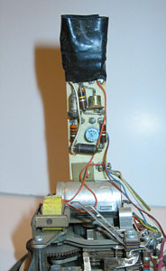 |
Ericotone Version 1
The first of the Ericotone ringers (commonly referred to as tweeters) are
found on the Earliest K5 chassis. The black tape at the top holds together a cluster of
neon tubes. I've seen a number of variations on this, so I think they changed it as they
went, maybe to work bugs out of the original design. It almost looks homemade.
The K5 chassis was not originally designed to carry the Ericotone, so they
had to modify it whenever a ringer was added.
|
 |
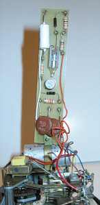
Ericotone Version 2
The next generation of the Ericotone is found on the K7. The K7 chassis
seems to have been a revision that allows for easy installation of a ringer without having
to make any changes to the original chassis configuration.
This chassis is identifiable by the use of large diodes (the red thing up
near the top) and the use of the Germanium transistor (the tiny oblong can in the center
of the board). |
 |
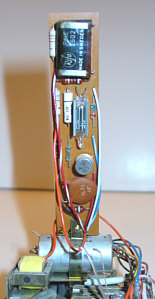
Ericotone Version 3
The final incarnation of the Ericotone is this model found on the K14
chassis. The electronics are the same as version 2, but you can see more modern
components are used. The big diodes have been replaced with tiny Zener diodes, and the
Germanium transistor was replaced with a more modern Silicon transistor. |
 |
ANI Ericotone
This is a special version of the Ericotone used in ANI phone service. I
won't get into the technical jargon. I'll just say that it's for use on party line
systems.
Personally, I have not been able to get these to work. The chassis is also
very different. I've been able to get the phone to ring, but not dial out, and vice versa.
I'm sure there's a way, but I see so few of these, I'm not going to take the time to
figure it out.
There's no volume adjustment for the Ericotone. |
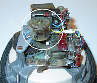 |
Internal Buzzer
The internal buzzer is the ringer used on all Ericofons NOT sold in the
USA. You can see it circled in the picture. It looks like a small can with a lid the size
of a dime (about 20mm) on it. You adjust the volume by turning the screw in the middle.
If you have a Swedish Ericofon, and you don't see this can, you have no ringer. |
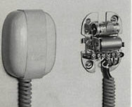 |
External Buzzer
In the early days, and later on in some countries, ringers were not
included in the Ericofon. You had to get a separate external buzzer that mounted on the
wall. |
Why
Some Ericofons light up when they ring:
Some people say their Ericofon lights up when it
rings, other's won't. Why the difference? Simply put, it all depends on where you
live. The telephone relies on current from the phone company (central office). The further
current has to travel, the more it drops. So, if you live close to a central office, your
current will be higher than for someone that lives ten miles down the road.
The Ericotone ringer circuit has some sensitive components. If these components get hit
with too much current, they will burn out. A limit needs to be placed in the circuit to
protect these parts. A neon tube acts as a "relief valve" of sorts. It just sits
there doing nothing until the current reaches a certain level. Once this level is
achieved, the neon tube will discharge the excess current to ground, lighting up as it
does. |